Distributed Control System (DCS)

MECO provides various solutions for automation and control of different processes in industrial sites, especially power plants and oil and gas sites. These solutions include systems under SPPAT2000-3000 license and domestically-manufactured MAPCS distributed control system.

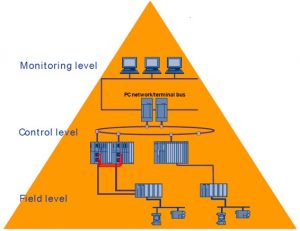
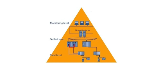
A distributed control system in large industrial sites consists of the following components:

Instruments/actuators are the devices that measure or control the process variables, such as temperature, pressure, flow, level, etc. They are connected to the controllers using one or more types of Field Bus technologies, such as Foundation Field Bus, DeviceNet and Profibus. The Field Bus reduces the cable usage by allowing many devices to share a single interface cable.

Controllers are the devices that control a part of the plant and are usually named after that part. They are connected to each other and to the higher level through a communication network called Plant Bus. The Plant Bus uses optical fiber as a physical interface for its high speed and noise immunity. It also uses Ethernet as a communication method with standard specification of IEEE802.3. The Ethernet combines twisted pair cables to connect the network endpoints and optical fiber for the site backbone connections.

Engineering Station (ES) is a computer that runs the system design and engineering software. ES performs all system engineering operations, such as downloading the software in controllers, modifying program logic, and making corrections and changes to the monitoring system graphic pages. ES is installed in the power plant central control room and is connected to both system buses: Terminal Bus and Plant Bus.

Operating Station (OT) is a computer that serves as operators’ workstation. On these computers, graphic pages are loaded in runtime (which are not editable). The terminal points are linked to the controllers via a server. Operators can view process values on these systems or send control commands to controllers through operating stations.

The system configuration is according to the diagram. 

OT communicates with controllers in two ways: 

  1. Client – Server 
  2. Stand-alone Station 

This system is supported by comprehensive and reliable software.

Scroll to Top